Municipal MBR
Biomass separation in designed biological treatment systems.
YiFu Trading
High-packing-density membrane modules for biomass separation in suitable municipal and industrial MBR systems.
Product overview
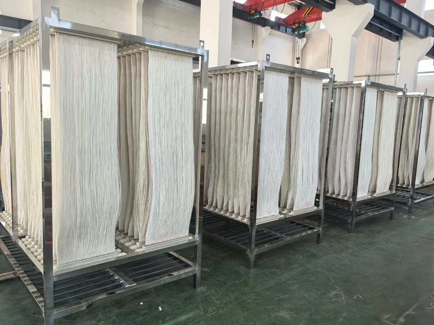
Hollow fiber MBR modules contain many small-bore membrane fibers connected to a permeate header. They can provide substantial membrane area within a compact tank footprint.
Fiber material, potting, support frame, aeration pattern, integrity management and cleaning procedure all affect practical performance.
Application fit
These are potential roles, not guaranteed performance claims. The complete process and verified product limits must be reviewed.
Biomass separation in designed biological treatment systems.
Use after contaminant-specific pretreatment and biological treatability review.
Compatibility assessment using current drawings, header details and operating conditions.
Selection
A similar-looking module may not be hydraulically or mechanically interchangeable. Obtain approved compatibility confirmation.
Supplier reference data
| Parameter | Published value | Selection note |
|---|---|---|
| Membrane type | Reinforced hollow fiber | Supplier reference configuration. Confirm the selected element and assembly before supply. |
| Fiber material | Hydrophilic modified RPVDF | Confirm the current material statement and chemical limits for the selected product. |
| Filtration direction | Outside-in | Supplier reference operating direction for the listed membrane elements. |
| MF pore size | 0.1 μm | Microfiltration option; select by separation duty and approved product data. |
| UF pore size | 0.03 μm | Ultrafiltration option; select by separation duty and approved product data. |
| Average permeate flux | 12–18 LMH | Supplier reference operating parameter, not a guaranteed project design flux. |
| Filtration / pause cycle | 8 / 2 min | Supplier reference cycle; final controls depend on wastewater and system design. |
| Operating TMP | 50–300 mbar | Coordinate operating, alarm and cleaning logic with the approved product documentation. |
| Operating temperature | 5–40°C | Confirm actual wastewater temperature and seasonal minimum before design. |
| pH range | 2–11 | Confirm continuous-operation and chemical-cleaning limits separately. |
| TSS reference range | 3–15 g/L | Supplier reference range; sludge condition and filterability also affect operation. |
| Maximum oil & grease reference | 150 mg/L | Not an automatic acceptance limit; oil form, pretreatment and fouling tendency require review. |
| Module frame options | AISI304 / AISI316 / SAF2205 | Select material against wastewater, cleaning chemicals and site environment. |
| Permeate pipe | Stainless Steel / PVC | Final material, size, connection and layout require project confirmation. |
| Air pipe | Stainless Steel / PVC | Final material, size, connection and air-distribution design require confirmation. |
Element range
Products are organized by pore size, membrane area and external dimensions. Supplier CM model numbers are not published, and YiFu model mapping will be added only after it is formally confirmed.
| Pore size | Membrane area | Element dimensions |
|---|---|---|
| 0.1 μm MF | 5.7 m² | 1125 × 480 × 30 mm |
| 0.1 μm MF | 7.1 m² | 1125 × 680 × 30 mm |
| 0.1 μm MF | 9.7 m² | 1300 × 680 × 30 mm |
| 0.1 μm MF | 11.3 m² | 1500 × 680 × 30 mm |
| 0.1 μm MF | 19.3 m² | 1300 × 1250 × 30 mm |
| 0.1 μm MF | 22.7 m² | 1500 × 1250 × 30 mm |
| 0.1 μm MF | 31.3 m² | 2000 × 1250 × 30 mm |
| Pore size | Membrane area | Element dimensions |
|---|---|---|
| 0.03 μm UF | 6.0 m² | 1125 × 480 × 30 mm |
| 0.03 μm UF | 8.8 m² | 1125 × 680 × 30 mm |
| 0.03 μm UF | 12.0 m² | 1300 × 680 × 30 mm |
| 0.03 μm UF | 14.0 m² | 1500 × 680 × 30 mm |
| 0.03 μm UF | 23.8 m² | 1300 × 1250 × 30 mm |
| 0.03 μm UF | 28.2 m² | 1500 × 1250 × 30 mm |
| 0.03 μm UF | 38.8 m² | 2000 × 1250 × 30 mm |
Engineering review
Module quantity and total membrane area should be selected from the design flow, wastewater type, MLSS, operating flux, temperature, tank dimensions, pretreatment, aeration and target permeate capacity. The supplier can configure different element quantities and total membrane areas for the project, but no fixed m³/day capacity table is published until the capacity unit and design basis are confirmed.
Actual design flux and operating conditions must be confirmed against wastewater characteristics, temperature, MLSS, pretreatment and fouling tendency. For preliminary calculations, review the MBR membrane selection guide, membrane area framework and MBR flux and sizing guide.
Send us your wastewater type, design flow, tank dimensions and existing membrane information for preliminary MBR module selection.
Verified visual references
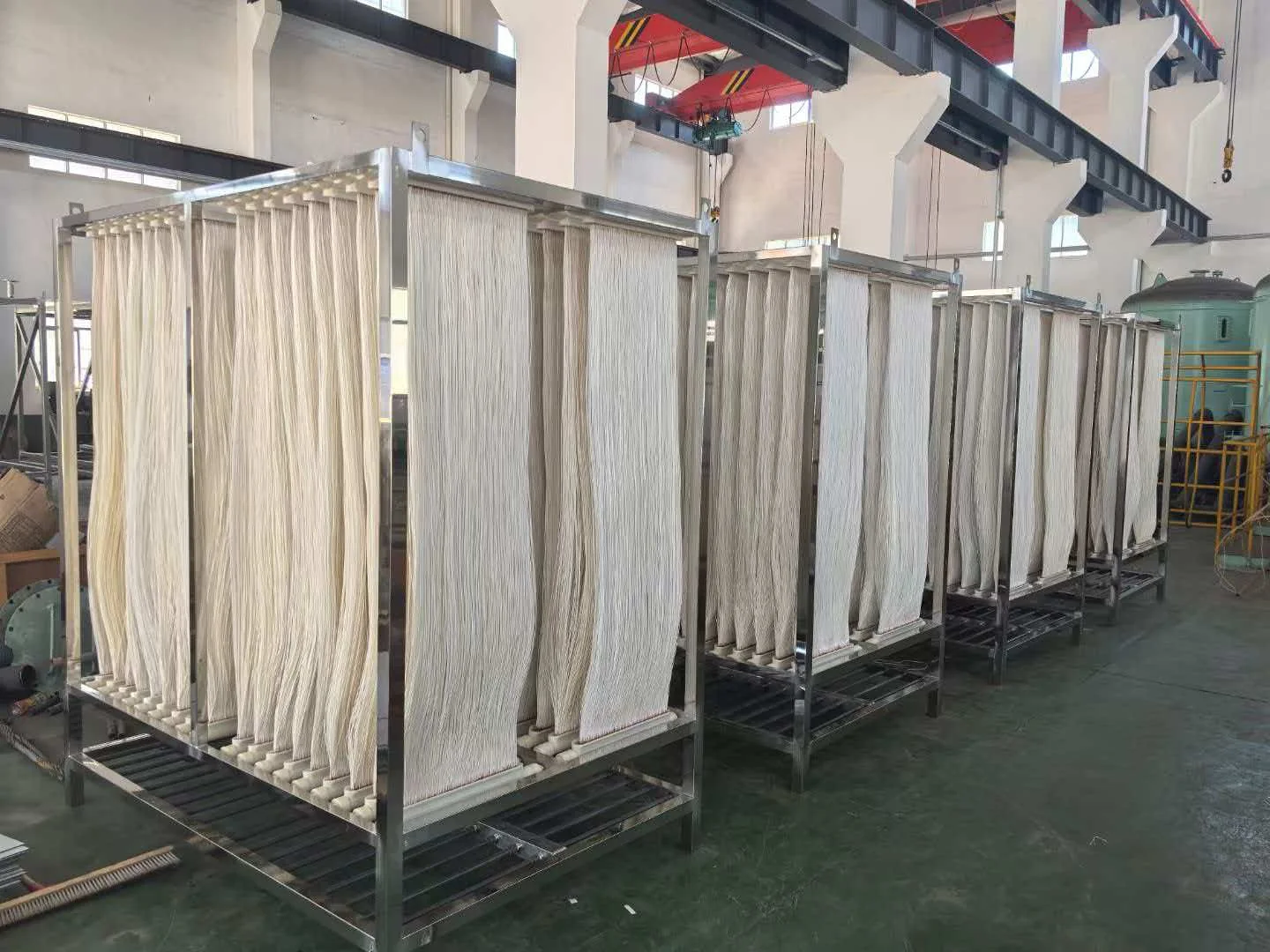
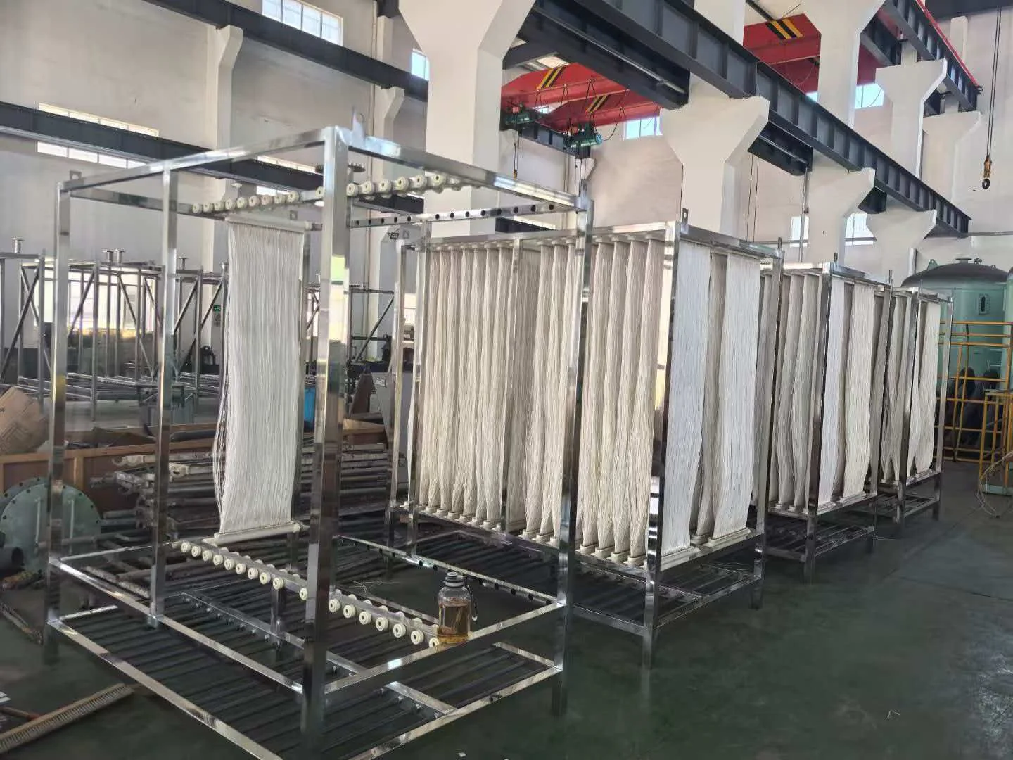
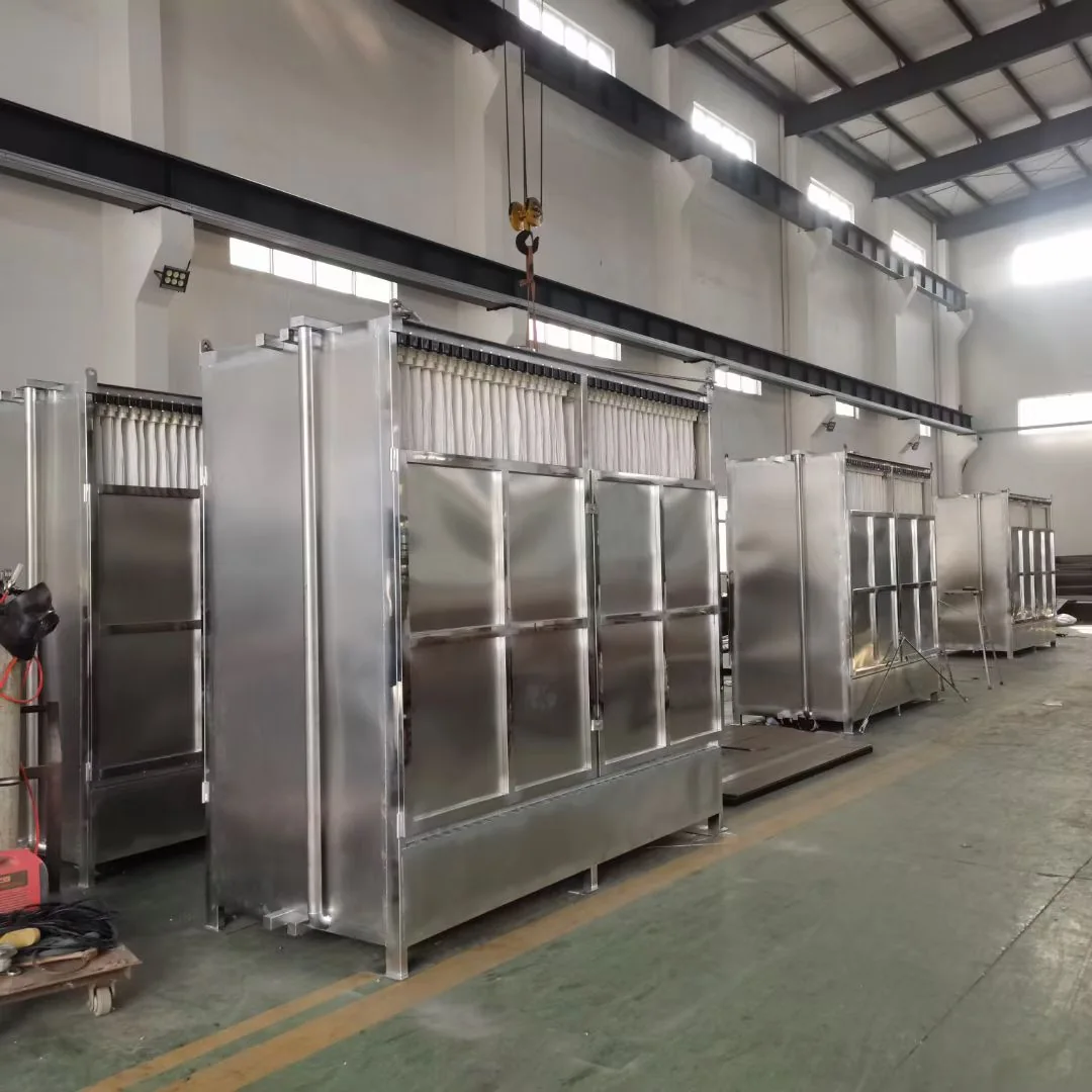
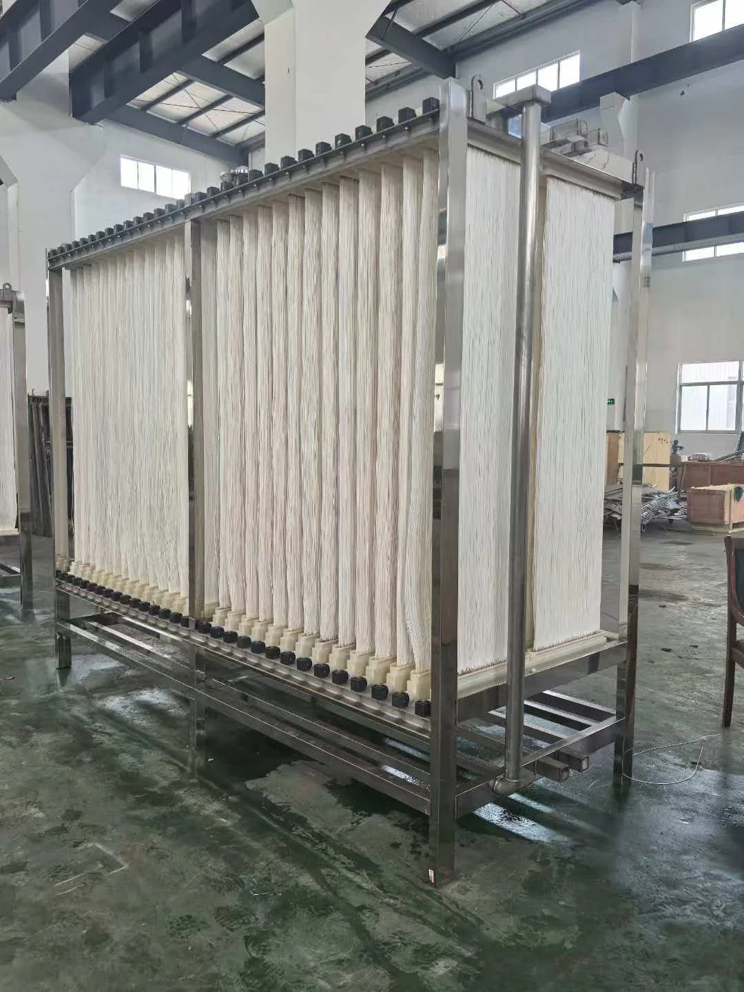
Current images document membrane elements, complete modules, cassette assembly and header/air-pipe details. Authorized installation, wastewater-tank, operating-site, factory, packing and shipment images can be added here as they are supplied.
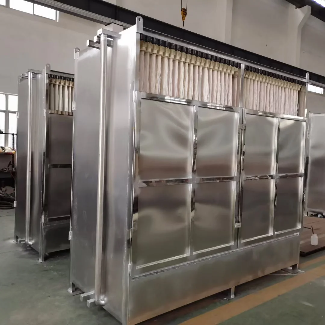
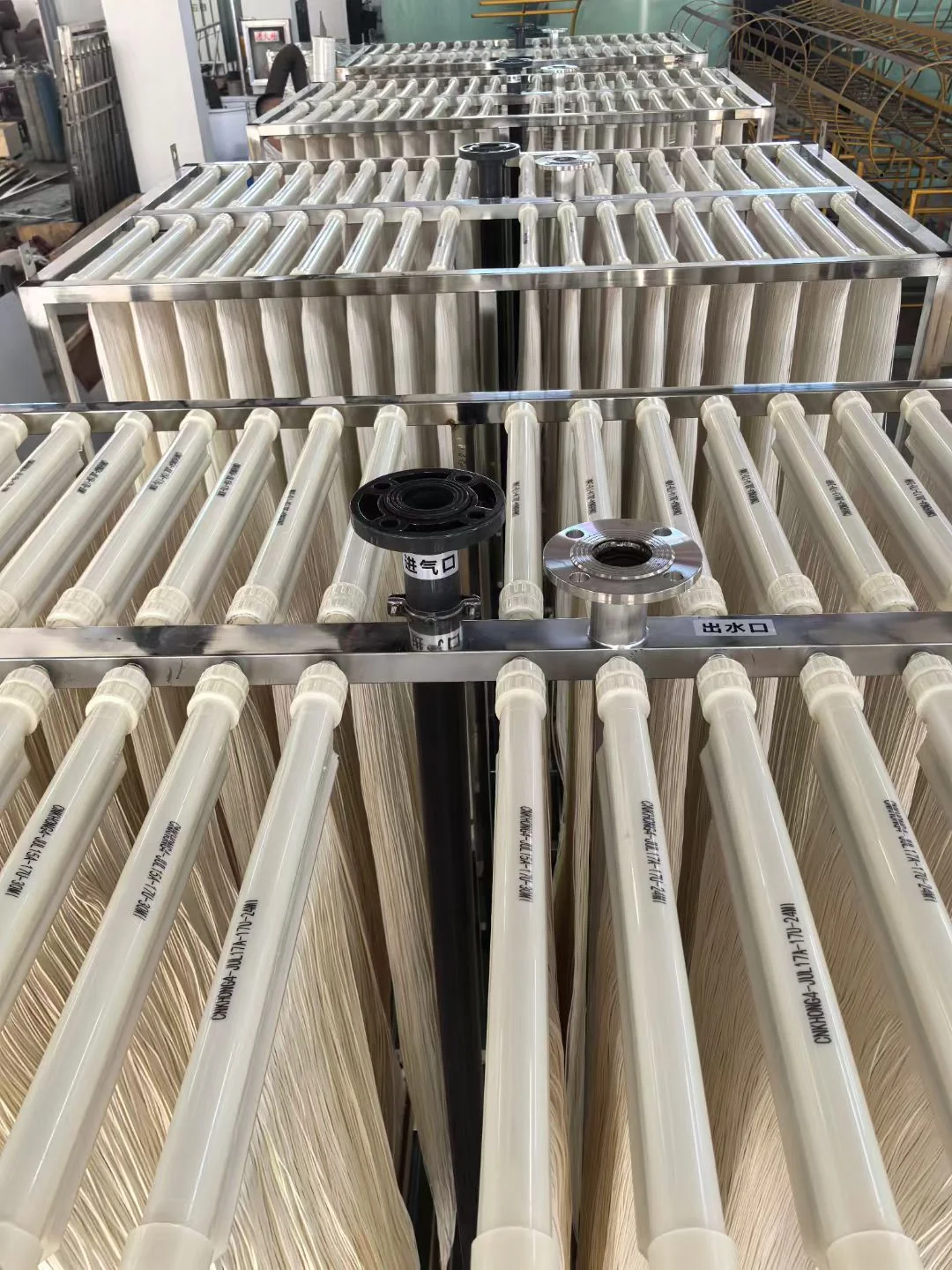
No country, customer, wastewater capacity or treatment result is assigned to these images because that information has not been provided with the visual references.
Related MBR pages
Hollow fiber performance depends on the complete biological, hydraulic and cleaning design.
Compare hollow fiber, flat sheet and selected ceramic MBR configurations.
Review MBR membrane modules →Compare a plate-type PVDF alternative for suitable tank and maintenance requirements.
Review flat sheet MBR membranes →Evaluate pretreatment, biological treatability and variable industrial contaminants.
Review industrial wastewater →Connect the membrane area and module arrangement to the municipal MBR process.
Review municipal wastewater →Start with the end-use quality target and downstream treatment requirements.
Review water reuse →Compare the complete interface—not only membrane area or external appearance.
Use the replacement checklist →FAQ
Some designs support backwash and others use different operating cycles. Confirm the selected product and system design.
Potential causes include abrasion, fatigue, handling, excessive pressure, chemical exposure or foreign objects. The actual cause needs investigation.
Send the current brand and model, module photos, drawings, dimensions, connections, installed quantity and operating conditions.
Share water data, flow, treatment objective or an existing membrane model. YiFu will coordinate the next technical questions.
For complete cassette sourcing, replacement review and export coordination, continue to the MBR membrane module supplier overview.
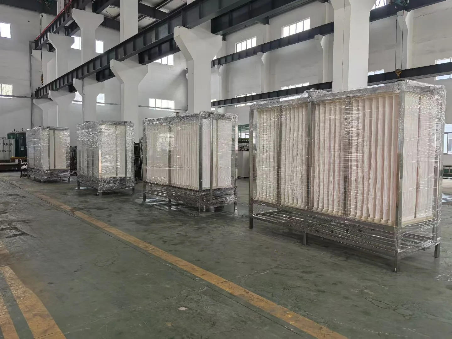
Factory and packing references
These supplied images show complete cassette frames, module assembly and protective packing. No customer, country, capacity or operating result is assigned because that information was not provided with the images.
Selection route
The element and cassette must be checked against the biological process, tank, aeration, cleaning and replacement interfaces.
Confirm screening, biology, MLSS, hydraulic loading and operating strategy before module selection.
Review wastewater MBR design inputs →Compare hollow fiber and flat sheet modules by tank fit, access, cleaning, integrity and lifecycle requirements.
Compare flat sheet and hollow fiber MBR →Use the existing model, drawing, connections, installed area and operating history for preliminary compatibility review.
Use the MBR replacement checklist →