Municipal wastewater MBR
Plate-type biomass separation where the biological process and membrane tank are designed for the required effluent and peak flow.
YiFu Trading
PVDF flat sheet membrane elements and cassette configurations for biomass separation in municipal and industrial MBR wastewater systems.
Product overview
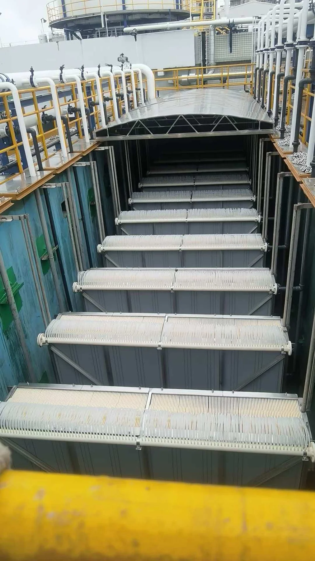
Flat sheet MBR membrane elements are arranged in cassettes and submerged in a membrane tank or zone. Permeate is withdrawn under negative pressure while the membrane retains suspended biomass.
The membrane module is one part of the MBR process. Screening, biological design, MLSS condition, aeration, operating flux, relaxation and cleaning determine whether the complete system can operate reliably.
Application fit
These are potential roles, not guaranteed performance claims. The complete process and verified product limits must be reviewed.
Plate-type biomass separation where the biological process and membrane tank are designed for the required effluent and peak flow.
Potential use after contaminant-specific pretreatment and biological-treatability review.
Preliminary compatibility screening using the existing model, element and cassette drawings, connections, tank and operating data.
Selection
Do not select a flat sheet MBR module from nominal area alone. Dimensions, header position, cassette spacing, aeration, hydraulic mode, cleaning limits and the biological operating conditions must be checked against an approved drawing and current datasheet.
Technical parameters
| Parameter | Published value | Selection note |
|---|---|---|
| Reference family | YF-FS-80 / YF-FS-100 / YF-FS-150 | YiFu reference designations based on manufacturing-partner data; confirm the current quotation datasheet. |
| Membrane construction | PVDF separation layer with PET support | Confirm membrane, support, frame and sealing materials for the selected configuration. |
| Nominal pore rating | 0.1 μm | Supplier reference value; actual separation depends on membrane integrity and system operation. |
| Reference membrane area | 0.8 / 1.0 / 1.5 m² per element | Corresponding to the YF-FS-80, YF-FS-100 and YF-FS-150 reference sizes. |
| Reference element dimensions | 1000 × 490 × 7 / 1160 × 518 × 7 / 1750 × 490 × 7 mm | Final replacement requires an approved drawing, tolerances and connection review. |
| Filtration mode | Submerged negative-pressure suction | Permeate cycle, relaxation and aeration sequence remain project-specific. |
| Design flux | Confirm for the wastewater and operating temperature | Do not convert clean-water or initial supplier test output into a guaranteed design flux. |
| Module configuration | Element count and cassette arrangement confirmed per project | Tank, lifting, header and air-scouring interfaces require approved drawings. |
| Cleaning limits | Confirmed for the selected product and project | Chemical, concentration, temperature, contact time and frequency must be approved before operation. |
Reference sizes
These reference values help screen a new or replacement inquiry. They do not replace the current datasheet, approved drawing or project flux review.
| YF model | Reference area | Reference dimensions | Initial supplier test output* |
|---|---|---|---|
| YF-FS-80 | 0.8 m² | 1000 × 490 × 7 mm | 320–480 L/element/day |
| YF-FS-100 | 1.0 m² | 1160 × 518 × 7 mm | 400–600 L/element/day |
| YF-FS-150 | 1.5 m² | 1750 × 490 × 7 mm | 600–900 L/element/day |
*Manufacturing-partner reference at 10°C and approximately -10 kPa using municipal wastewater. These values are not a guaranteed wastewater design flux or site-performance promise.
Application boundary
Flat sheet modules may suit projects that value plate-based access, defined cassette layouts and submerged biomass separation. The configuration should be evaluated with the tank, aeration and operating strategy.
They should not be selected where the wastewater is not biologically treatable, where oils or chemicals exceed approved limits, where screening is inadequate, or where an existing cassette cannot accept the proposed dimensions and connections.
Provide the existing brand, model, nameplate, drawings, photos, dimensions, membrane area, connection details, tank size, design flow and MLSS.
Review replacement requirementsCompare the process roles and selection factors across MBR membrane configurations.
Review MBR membranes →Compare packing density, access, integrity, cleaning and replacement factors.
Read the comparison →Place the module within the biological, hydraulic and cleaning design.
Review the application →FAQ
No. Biological treatability, screening, oils, chemicals, temperature, sludge condition and approved product limits must be reviewed.
Only after dimensional, hydraulic, connection, cassette, aeration and operating compatibility are confirmed in writing.
Use representative wastewater, temperature, MLSS, fouling risk, operating cycle and available supplier or pilot evidence. A catalogue test output is not a universal design flux.
Send the required quantity and destination plus the existing model or new-system flow, wastewater type, tank, MLSS, drawings, dimensions and connection requirements.
Share water data, flow, treatment objective or an existing membrane model. YiFu will coordinate the next technical questions.
For broader module comparison and China sourcing support, review the MBR membrane supplier and replacement options.
Check whether a flat sheet configuration fits the process, tank, aeration and maintenance plan.
Review MBR module selection →Convert project flow and a verified net flux into preliminary area and whole modules.
Review the area calculation →Define the wastewater, operating cycle, TMP, temperature and availability behind the design flux.
Review flux and sizing →Real product references
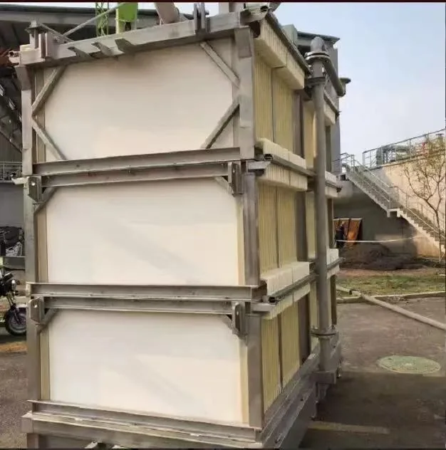
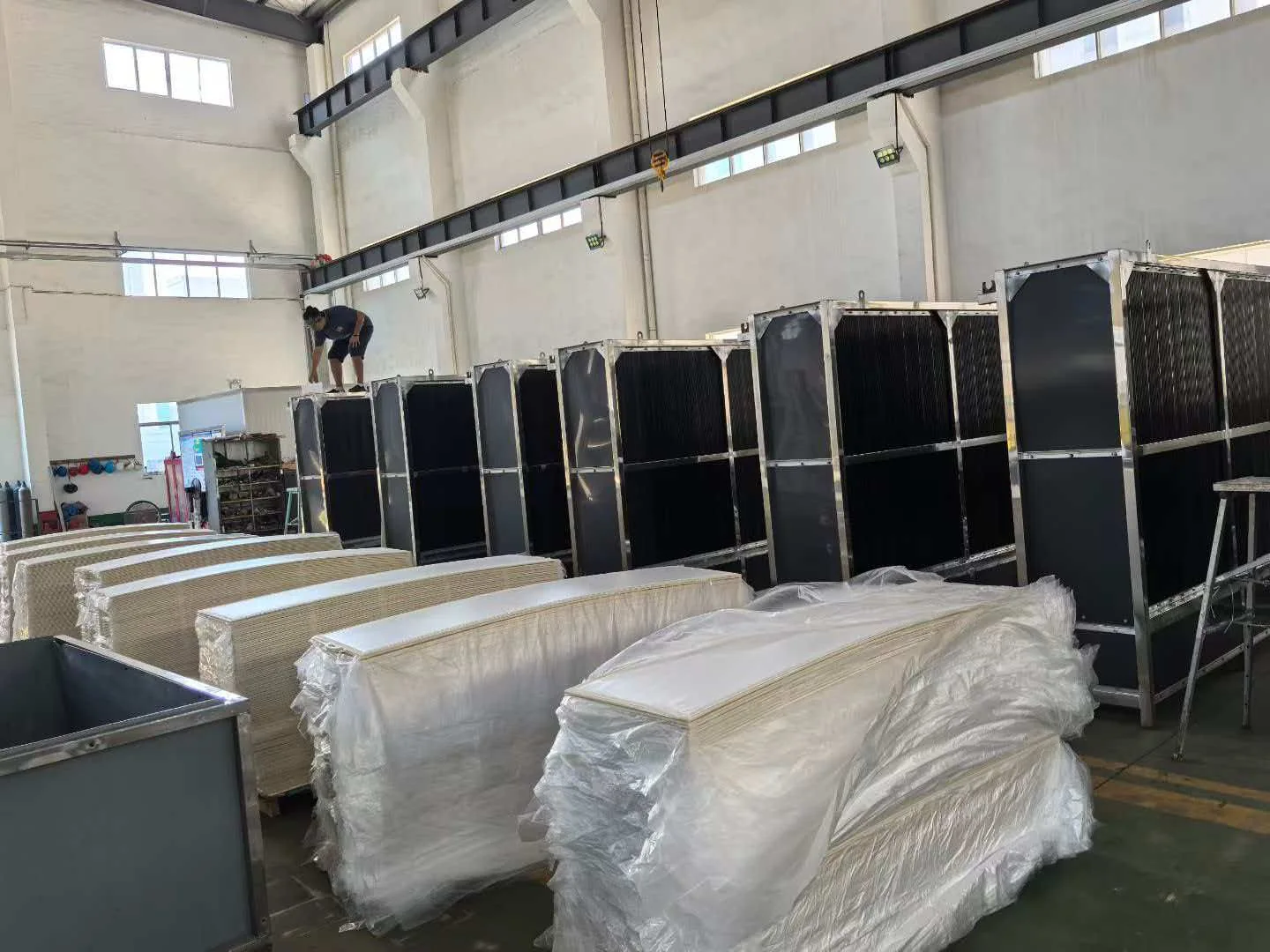
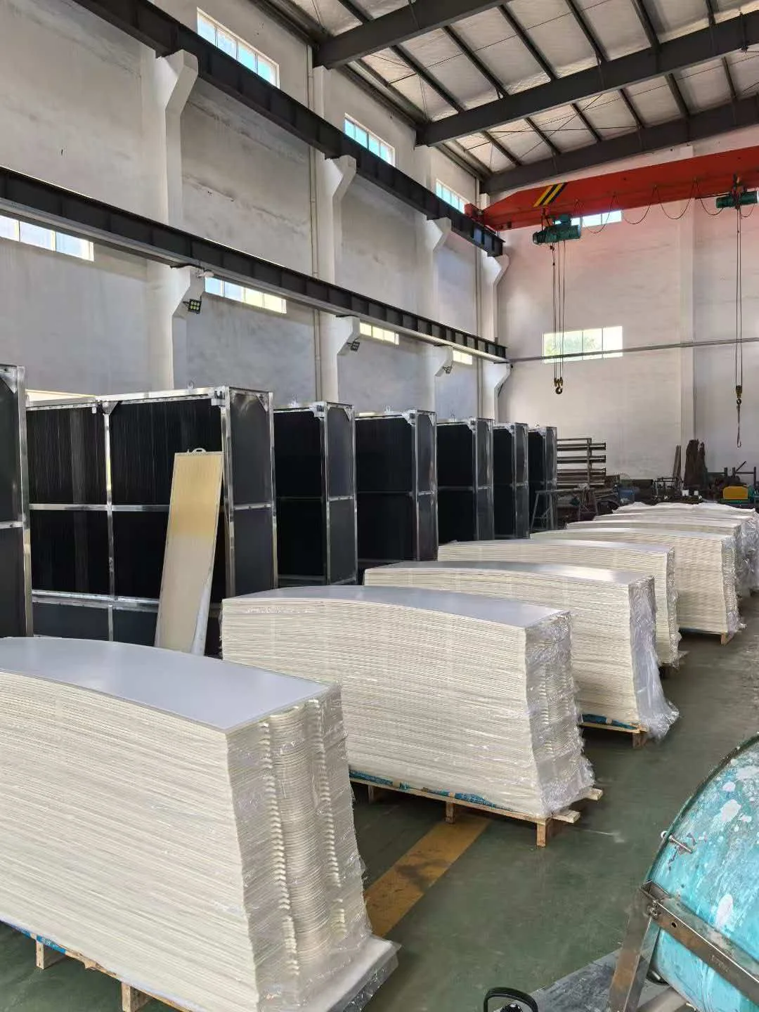
The supplied images document individual plate-type membrane elements, a complete cassette, factory assembly and packed elements. They are product and manufacturing references, not project-performance claims.

Related selection paths
Configuration selection should connect the element and cassette to the wastewater, tank, operating strategy and target effluent.